Skip to content
+86 13715293763
sales2@xcepcb.com
Mon-Fri 9:00AM - 6:00PM CST, UTC+8
Search
Home
PCB Manufacturing
Microwave PCB Manufacturing
RF PCB Manufacturing
Multilayer PCB Manufacturing
Antenna PCB Manufacturing
Rogers PCB Manufacturing
Taconic PCB Manufacturing
Heavy Copper PCB Manufacturing
PCB Assembly
Products
PCB Products
F4B PCB
Taconic PCB
Rogers PCB
Hybrid PCB
Multilayer PCB
Materials
Material Selection Center
Rogers PCB Materials
Taconic PCB Materials
F4B (Wang Ling)
ZY (Zhong Ying)
Capability
PCB Equipments
Quality Assurance
About us
Blog
Materials Encyclopedia
Material Selection Guide
Manufacturing Processes & Equipment
Design Guides
Application Cases
Industry Trends & Market Insights
PCB Basics
Sourcing Guide
Reliability Testing
FAQs
Contact Us
Get A Quote
All
Materials Encyclopedia
Material Selection Guide
Manufacturing Processes
Design Guides
Application Cases
Industry Trends
PCB Basics
Sourcing Guide
Reliability Testing
Search
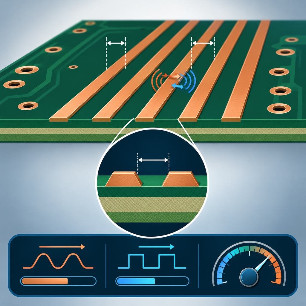
Introduction and Function of Trace Width and Spacing in High-Frequency PCB Processing
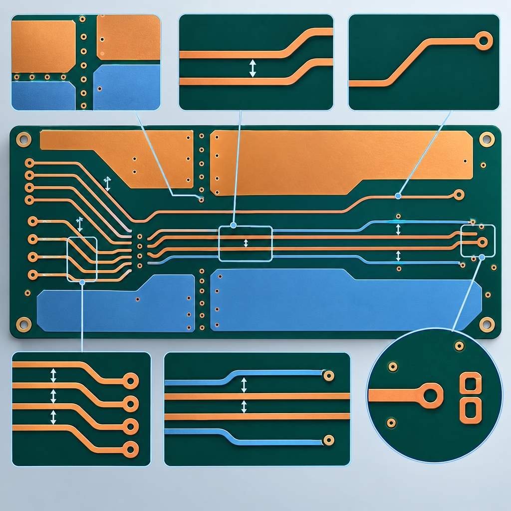
Wiring Recommendations for High-Frequency PCB Design and Production
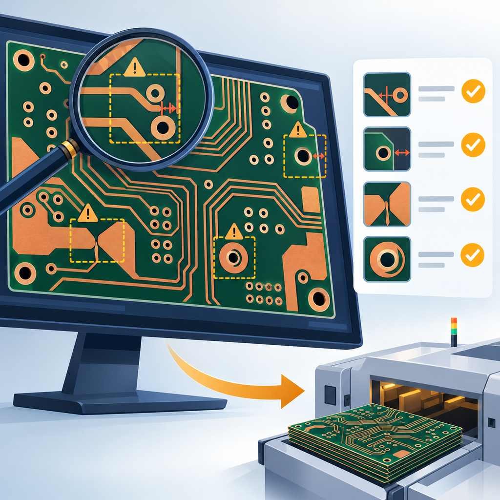
What is Design Rule Check, its performance and role in PCB manufacturing?
High-Frequency PCB Microstrip Line Design: How to Ensure Impedance Consistency with 0.05mm Line Width?
Hybrid PCB Stack-up Analysis: Key Process Considerations for Rogers RT5880 and FR4 Integration
High-Frequency PCB Microstrip Design: Ensuring Impedance Consistency at 0.05mm Trace Width
PCB Via Guidelines for Multi-layer Circuit Board Manufacturing
Multi-layer PCB Layer Count Design Principles
RF PCB Design Guidelines and Considerations
Standard PCB Layout Guidelines
RF Microwave Circuit Board Design Tools
Sample excerpt-3
×
Table of Contents
Table of Contents
PCB Assembly
Prototype PCB Assembly
Turnkey PCB Assembly
Flex PCB Assembly
Box Build Assembly
Contract Manufacturing
Through-hole Assembly
BGA Assembly
Quick Turn PCB Assembly
Low Volume PCB
PCB Assembly FAQ
PCB Assembly Process
PCBA Services
PCB Stencil
Components Sourcing
IC Programming
Conformal Coating
Selective Soldering
BGA Reballing
No Clean Flux
Cable Assembly
Wire Harness Assembly
Quality
Quality Control
DFA Check
A.O.I.
E-Test
X-Ray Inspection
Flying Probe Test
In-Circuit Testing
Functional Testing
3D Solder Paste Inspection
First Article Inspection
Application
Industrial PCB
Automotive PCB
Medical PCBA
Aerospace PCB
Lighting PCB
Consumer Electronics
Telecommunication PCB
Military and Defense
Security Equipment
IOT PCB
Power and New Energy
Resources
Panel Requirements for Assembly
Required Files for PCBA
IPC standard for assembly
PCB Files Format
PCB Design
Schematic to PCB
Printed Circuit Board
PCB Prototype
Quick turn PCB Fabrication
Multilayer PCB
HDI PCB
Flexible PCB
Rigid Flex
Ceramic PCB
Heavy Copper PCB
Antenna PCB
High Frequency PCBs
Metal Core PCB
Glass PCB
High-TG PCB
PCB Impedance Control
LED PCB
RF PCB
Rogers PCB
Taconic PCB
Teflon PCB
Arlon PCB
Nelco PCB
Megtron PCB
ISOLA PCB
Quality
Quality Control
PCB DFM Check
A.O.I
E-Test
X-Ray
Flying Probe Test
PCB Surface Finish
HASL Lead Free
Immersion Gold(ENIG)
Gold Plating(Hard Gold)
ENEPIG
OSP PCB
Immersion Tin
Immersion Silver
Printed Circuit Board
PCB Materials
Drilling
Etching
Plating
Lamination
Solder Mask
Silk Screen
Dry Film
Drills & Throughplating
Blind vias
Buried vias
Annular Ring
Half Hole PCB
Plated Slot
Via In Pad
Backdrill
Via Covering
Profiles
Milling
V-Scoring
Depaneling
PCB Stackup
Multi-Layer Laminated Structure
4 Layer PCB Stackup
6 Layer PCB Stackup
8 Layer PCB Stackup
10 Layer PCB Stackup
Flex PCB Stackup
Rigid Flex PCB Stackup
Aluminum PCB Stackup
Resources
Manufacturing Tolerances
Trace Impedance Calculator
RoHs Lead Free
PCB Shelf Life
PCB Engineering Questions
PCB Manufacturing FAQs
Open toolbar
Accessibility
Accessibility
Increase Text
Increase Text
Decrease Text
Decrease Text
Grayscale
Grayscale
High Contrast
High Contrast
Negative Contrast
Negative Contrast
Light Background
Light Background
Links Underline
Links Underline
Readable Font
Readable Font
Reset
Reset
Contact Us
Contact Us
Feedback
Feedback