A practical introduction to high-frequency PCBs — what counts as high frequency, how Dk and Df shape performance, which materials to pick and where these boards are used.
A high-frequency PCB is a specialized printed circuit board built to transmit high-speed signals with minimal loss. In most cases, a board operating above 1 GHz counts as high-frequency — the territory of RF, microwave, millimeter-wave and high-speed digital design, where signal integrity and electrical stability decide whether the product works.
As 5G, automotive electronics, IoT, satellite communication and cloud computing keep evolving, demand for high-frequency PCB manufacturing is growing fast. Compared with traditional FR-4, these materials offer lower dielectric loss, more stable impedance, lower moisture absorption and better thermal reliability.
Today you will find high-frequency PCBs in 5G base stations, automotive radar systems, satellite communication equipment, Wi-Fi 6 and Wi-Fi 7 devices, aerospace electronics, high-speed servers and RF modules.
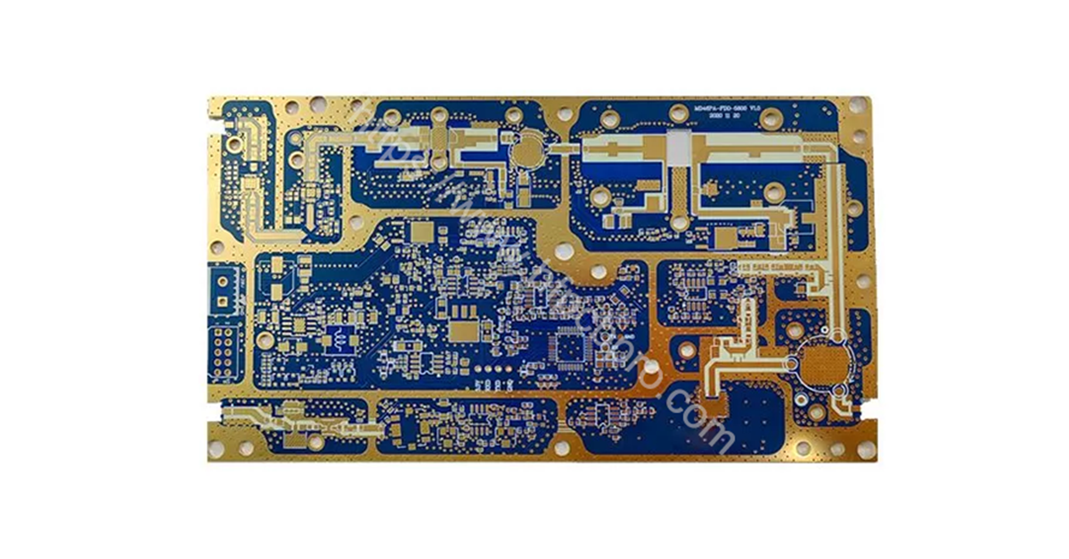
Modern electronic systems are moving more data at higher frequencies than ever before — and standard materials struggle to keep up. At high frequencies, even small inconsistencies in the board cause signal attenuation, electromagnetic interference, increased insertion loss, impedance instability and data transmission errors.
High-frequency PCB technology answers with advanced laminate materials and optimized design techniques. The primary goal is simple to state and hard to do: maintain signal integrity while minimizing loss during transmission.
Two numbers decide most material conversations — here is what each one actually controls.
Dk measures how much electrical energy the material stores. Lower Dk lets signals travel faster — transmission speed is inversely proportional to the square root of Dk (v ∝ 1/√Dk). Lower Dk means faster signal transmission; higher Dk means greater delay.
Stable Dk matters as much as low Dk: fluctuations hit impedance control and timing accuracy directly. Typical values:
| Material | Typical Dk |
|---|---|
| PTFE | 2.2 |
| Rogers RO4003C | 3.38 |
| Standard FR-4 | 4.2–4.8 |
| Ceramic-filled laminates | 6–10+ |
Df measures how much signal energy turns into heat during transmission. Lower Df means better RF signal quality and less attenuation. Typical values:
| Material | Typical Df |
|---|---|
| Rogers RT5880 | 0.0009 |
| PTFE materials | 0.0008–0.002 |
| Standard FR-4 | 0.015–0.025 |
For demanding applications — 77 GHz automotive radar, 5G millimeter-wave antennas, high-speed networking and aerospace RF systems — ultra-low-loss materials are not a luxury, they are the entry ticket.
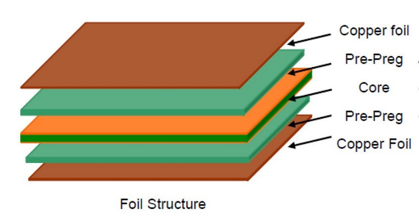
Controlled impedance is one of the most important requirements in high-frequency manufacturing. Poor matching causes reflections, transmission loss and unstable RF performance. Typical structures: 50-ohm single-ended traces, 90-ohm and 100-ohm differential pairs.
Accurate control means carefully optimizing trace width, copper thickness, dielectric thickness, PCB stackup and ground reference planes. Design software such as ADS, HFSS and HyperLynx is standard practice for verifying impedance before production.
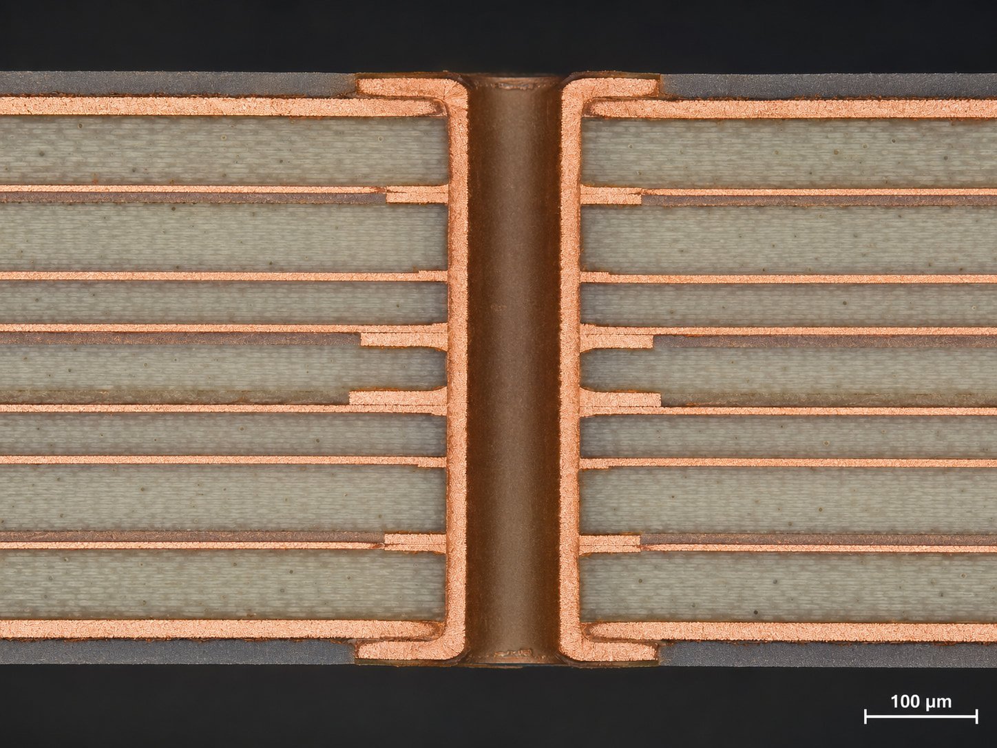
Moisture absorption quietly shifts electrical properties — once water enters the substrate, both Dk and Df drift, and RF performance becomes unstable. Advanced materials such as PTFE and LCP offer extremely low absorption, which is what makes them suitable for harsh outdoor and aerospace environments.
Thermal reliability matters equally. High-frequency materials must hold dimensional stability through thermal cycling and soldering, which means: low coefficient of thermal expansion (CTE), high glass transition temperature (Tg), strong copper adhesion and excellent heat resistance.
Four material families cover most high-frequency designs — each with a distinct cost-performance position.
PTFE is widely regarded as the best choice for microwave and millimeter-wave work thanks to its ultra-low loss. Popular laminates: Rogers RT5880 and RT5870, plus Taconic RF materials. Applications include satellite communication, aerospace systems, automotive radar and RF test equipment.
Hydrocarbon ceramic laminates combine excellent RF performance with far easier manufacturing than pure PTFE. The common products are Rogers RO4350B and RO4003C, widely used in 5G antennas, RF amplifiers, power dividers and wireless communication modules.
Modified epoxy laminates are the cost-effective option for mid-frequency applications, staying compatible with standard FR-4 processing. Typical uses: Wi-Fi modules, Bluetooth devices, consumer electronics and IoT hardware.
LCP offers ultra-low moisture absorption, high flexibility and excellent millimeter-wave performance — increasingly used in wearable electronics and flexible RF circuits.
Five application areas account for most of the demand.
High-frequency PCBs support the high-speed signal transmission that 5G infrastructure and millimeter-wave communication systems require.
Radar systems at 24 GHz and 77 GHz depend on low-loss materials for accurate target detection and signal stability.
Satellite systems need ultra-reliable RF transmission over long distances — which is why PTFE-based materials are the preferred solution.
As networking speeds push beyond 400G and 800G, high-frequency PCB technology becomes critical for servers and optical communication systems.
Smartphones, wireless charging systems, wearable devices and Wi-Fi 7 products all benefit from advanced RF PCB technology.
High-frequency PCB technology has become an essential part of modern electronics. Compared with standard FR-4, these materials deliver lower Dk, lower Df, better impedance stability, lower moisture absorption and improved thermal reliability.
As systems keep moving toward higher frequencies and faster data rates, the importance of high-frequency design and manufacturing will only grow. For the board-level design rules, continue with our high-speed high-frequency PCB design guide.
Common questions about high-frequency PCBs, materials and design.
Generally anything operating above 1 GHz — RF, microwave, millimeter-wave and high-speed digital designs where material behavior dominates performance.
Dk sets signal transmission speed and, together with trace geometry, the impedance. If Dk wanders, impedance and timing wander with it — so stability matters as much as the absolute value.
For ultra-low loss, PTFE laminates such as Rogers RT5880 lead the field; for easier processing and better cost balance, hydrocarbon ceramics like RO4350B are the workhorse choice.
Loss is signal energy converted into heat instead of reaching the receiver — at microwave frequencies, FR-4's loss alone can erase an entire link budget.
5G communication, automotive radar, satellite systems, aerospace electronics, RF modules and high-speed data centers — anywhere signals live above 1 GHz.
Tell us your frequency band and application. Our engineering team will recommend the right material, review your stack-up and quote your high-frequency PCB.
Get An Engineering Review → Fast Reply on WhatsApp