Two flagship PTFE laminates compared — Dk 2.33 vs 2.20, Df, standard panel sizes, thickness options and the applications each one fits best.
High-frequency circuit design lives and dies by stable dielectric performance, especially in RF, microwave and millimeter-wave systems. RT5870 and RT5880 — both PTFE-based laminates — are widely used in antenna systems, radar modules, satellite communications and 5G infrastructure for their low dielectric loss and excellent electrical stability.
Both are PTFE laminates engineered for high-frequency use, offering low Dk and ultra-low Df:
RT5880’s slightly lower Dk and loss make it the better fit for ultra-high-frequency and low-loss transmission designs.
Same laminate family, two different optimizations — the comparison below shows where each one fits.
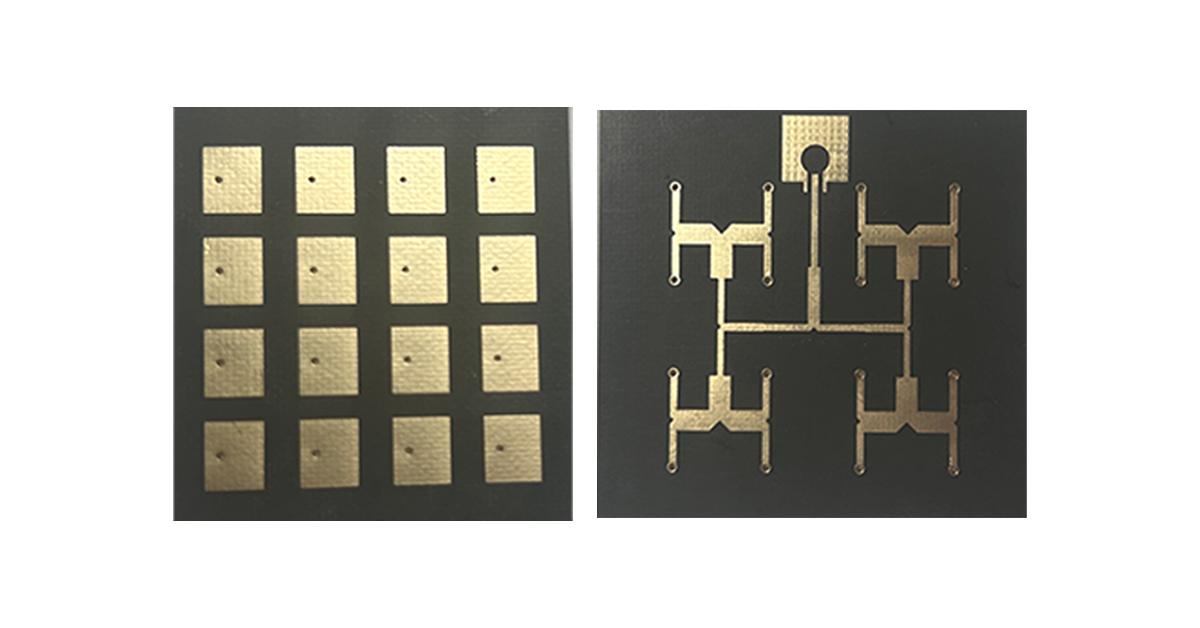
Typical applications for both materials:
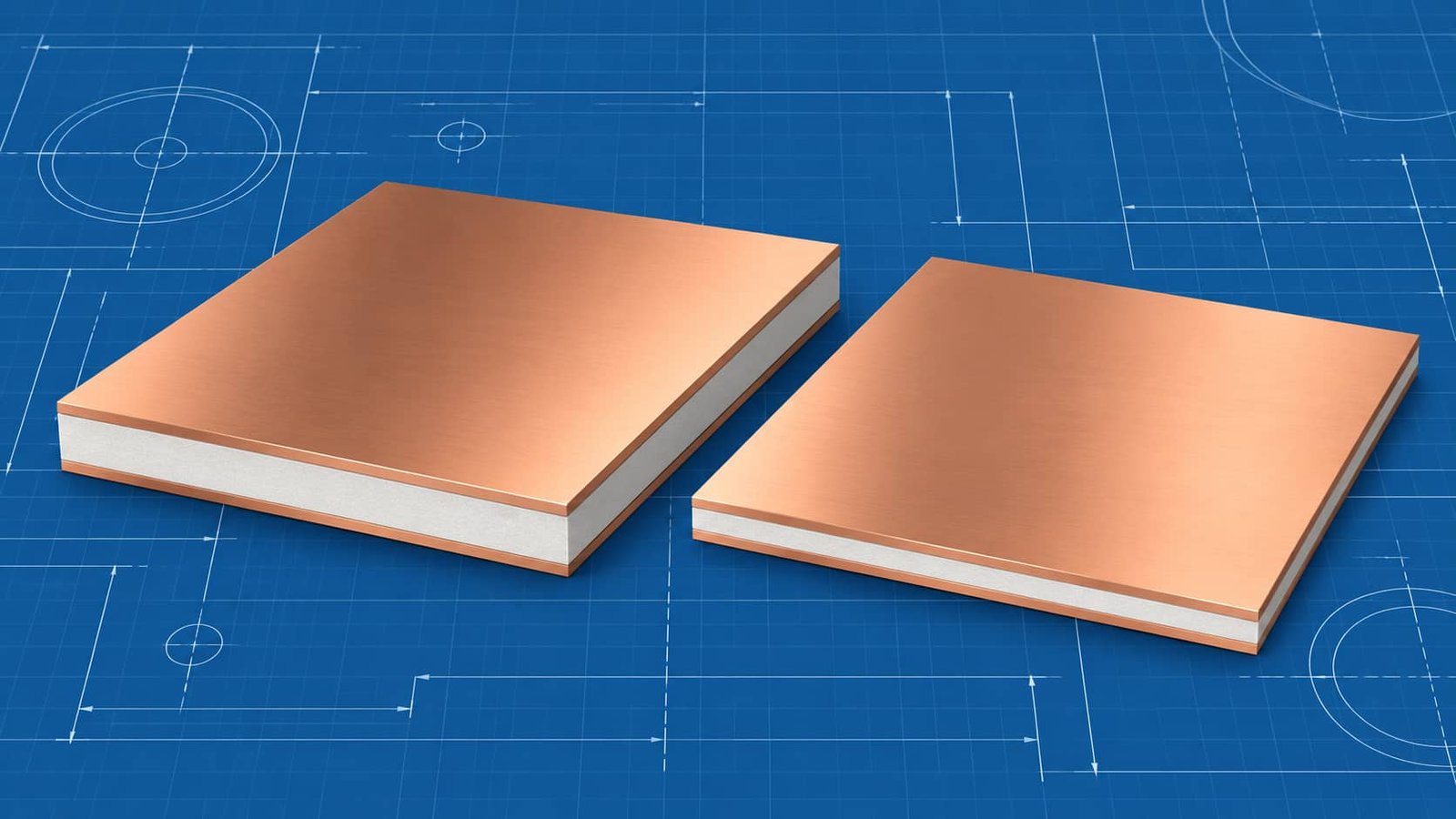
Both laminates come in industry-standard sheet formats that support scalable PCB manufacturing:
These configurations suit compact RF modules as well as large antenna array systems.
The main advantages of RT5870 and RT5880 include extremely low signal loss at microwave frequencies, stable dielectric performance across frequency changes, excellent dimensional stability, suitability for multilayer RF and hybrid PCB structures, and reliable performance in harsh environmental conditions.
That mix is exactly why aerospace, defense and high-speed wireless systems keep specifying them.
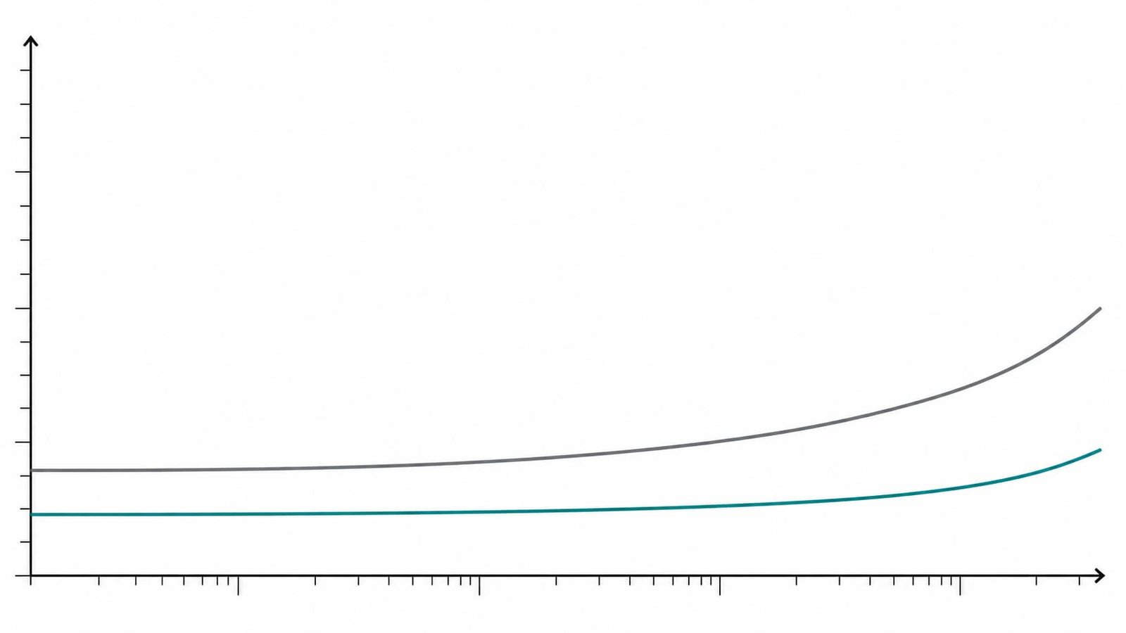
Both materials come from Rogers Corporation, a global leader in high-performance engineered materials for RF and microwave applications. Its RO4000 and RO3000 series laminates are widely adopted in next-generation wireless communication systems. For the hydrocarbon-ceramic alternative with easier processing, see our RO4350B overview.
When selecting between RT5870 and RT5880, engineers typically evaluate operating frequency range, insertion loss requirements, impedance stability, thermal and mechanical constraints, and the manufacturing cost versus performance balance.
RT5880 is often preferred for ultra-low-loss antenna designs, while RT5870 wins where cost-performance balance matters. If you are still building the fundamentals, start with our high-frequency PCB guide.
Common questions about Rogers RT5870 and RT5880 laminates.
RT5880 runs a lower dielectric constant (2.20 vs 2.33) and lower loss tangent, so it wins on ultra-high-frequency, low-loss designs; RT5870 offers a better cost-performance balance for general RF work.
Yes — both are widely used in 5G antenna and RF front-end designs thanks to their stable performance across frequency and temperature.
0.254 mm and 0.508 mm are the volume favorites, though the full range runs from 0.127 mm up to 3.175 mm.
Frequently — usually as hybrid stack-ups where FR-4 handles the non-RF layers, which keeps cost down without sacrificing RF performance.
Standard sheets come in 12 × 18 and 18 × 24 inches, with 0.5 oz or 1 oz copper cladding.
Send us your stack-up and material combination. Our engineering team will review the lamination plan, drilling and plating strategy, then quote your hybrid RF board.
Get An Engineering Review → Fast Reply on WhatsApp