High-Frequency PCB Insights & Resources

Technical guides, material comparisons and process insights on high-frequency, RF and microwave PCB manufacturing.

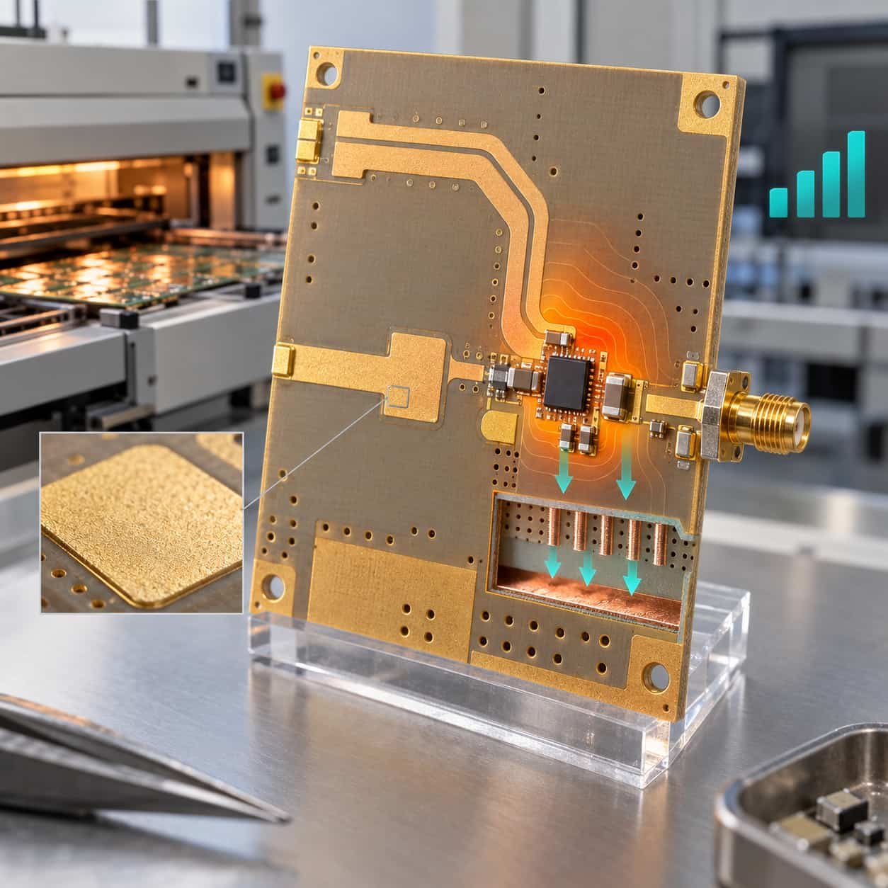
High-power RF RO4350B board with thermal vias under an amplifier, ENIG gold pads and a reflow oven with signal strength markers

Immersion Gold Rogers RO4350B High-Frequency Circuit Board: The Ideal Solution for High-Power RF Applications

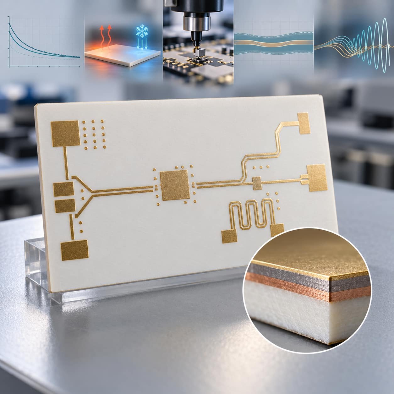
RT/duroid 5880 PTFE panel with five advantage callouts for loss, environment, assembly, impedance and frequency reach, finished in ENIG gold

Immersion Gold Rogers 5880 RF Circuit Board: The Premium Solution for High-Frequency Design

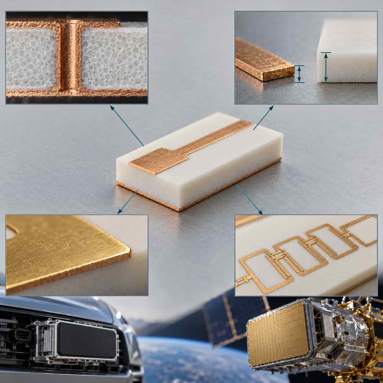
RT/duroid 5880 cross-section with four arrows leading to decision cards for isotropy and vias, CTE, gold finish and filter tolerance

Immersion Gold Rogers 5880 High-Frequency Circuit Board: The Core Choice for Superior RF and Microwave Performance

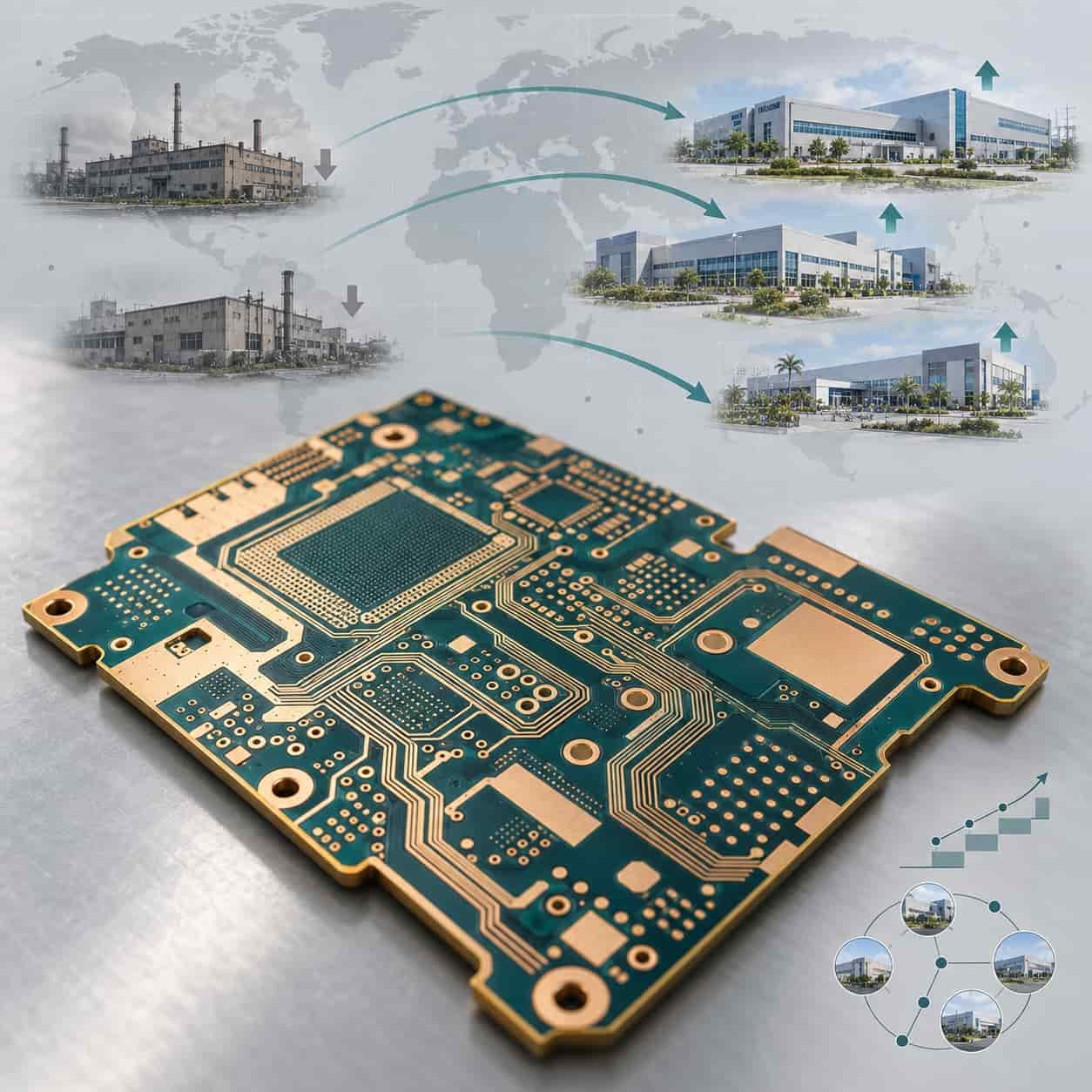
World map grid with fading and brightening PCB factory silhouettes, migration arrows and technology ladder for capacity relocation

Large-Scale PCB Factory Relocations and Closures: Key Drivers and Industry Implications

Rising demand curve from 5G to AI above a process hurdle with four barriers of cost, precision, supply and talent

Key Considerations in High-Frequency & High-Speed PCB Manufacturing: Opportunities and Challenges

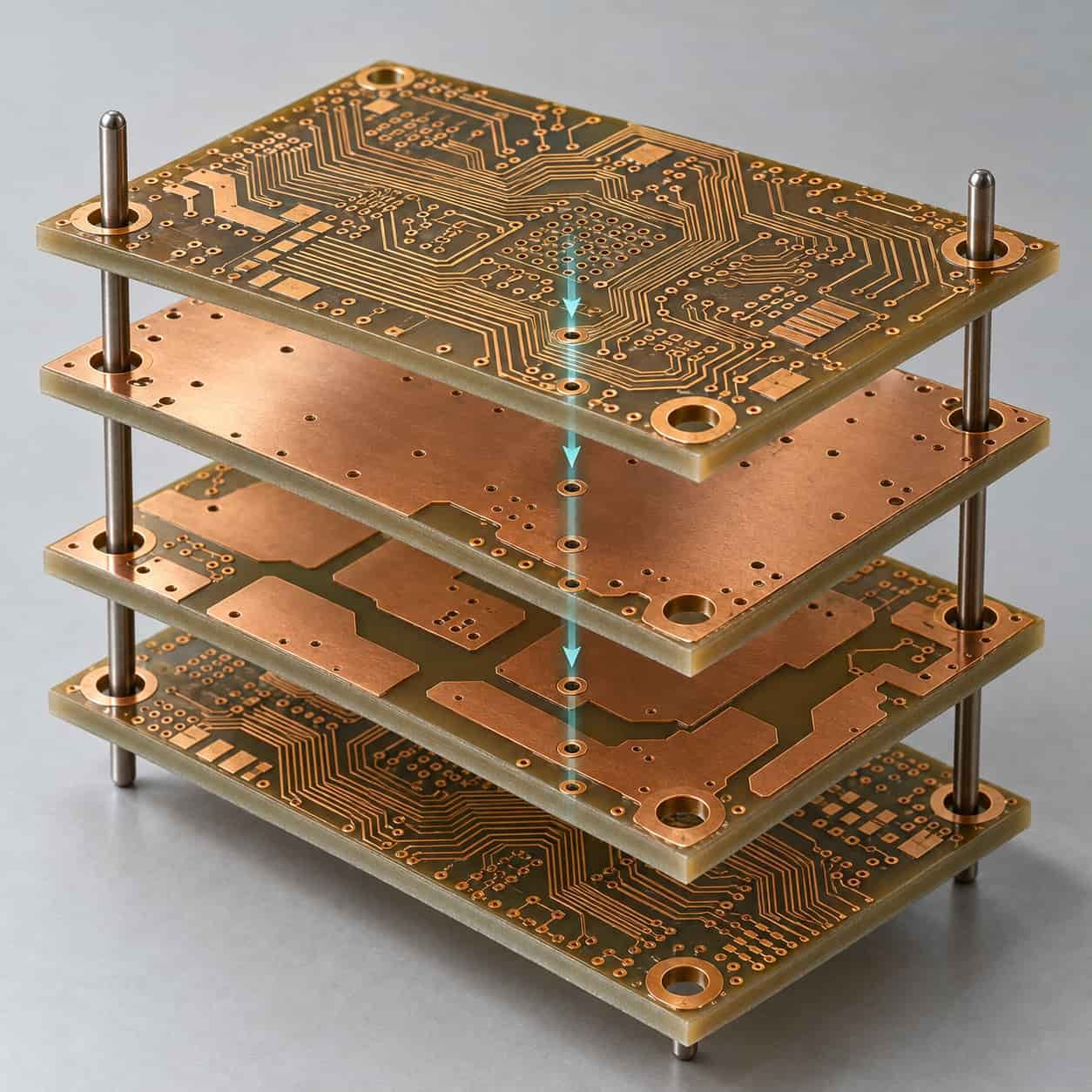
Exploded four-layer ENIG RO4350B stack with signal, ground and power planes, alignment pins and a thermal path

Key Features of 4-Layer Immersion Gold Rogers RO4350B High-Frequency PCB

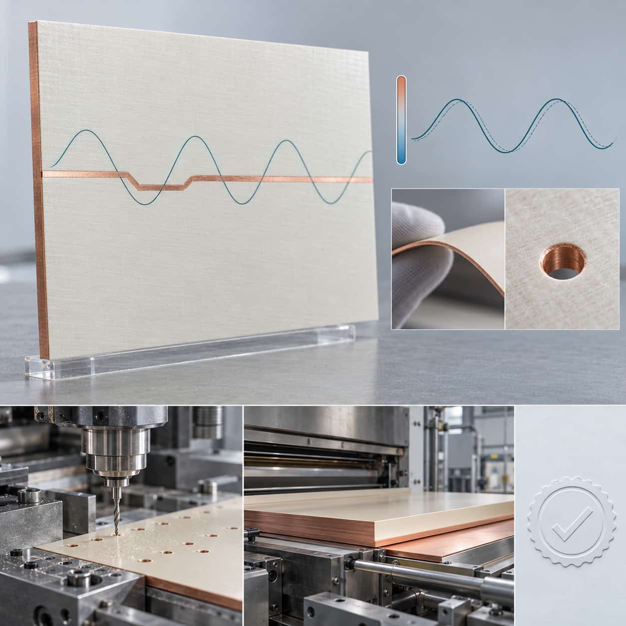
DiClad 880 laminate panel holding phase across temperature, with mechanical toughness and standard process icons and a compliance seal

Rogers DiClad® 880Key Properties of Rogers DiClad® 880 High-Frequency Circuit Board MaterialRogers DiClad® 880

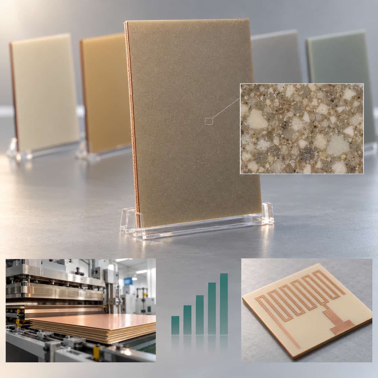
RO4003C laminate panel highlighted within its family row, with processability, volume economics and antenna icons beneath

Performance and Applications Analysis of High-Performance Rogers RO4003C High-Frequency Board

Rogers RO4003C delivers superior HF performance (Dk=3.38±0.05, Df=0.0027), mmWave-ready process compatibility, and 5G/radar/satellite applications. Prioritize UL-certified suppliers with VNA test reports.
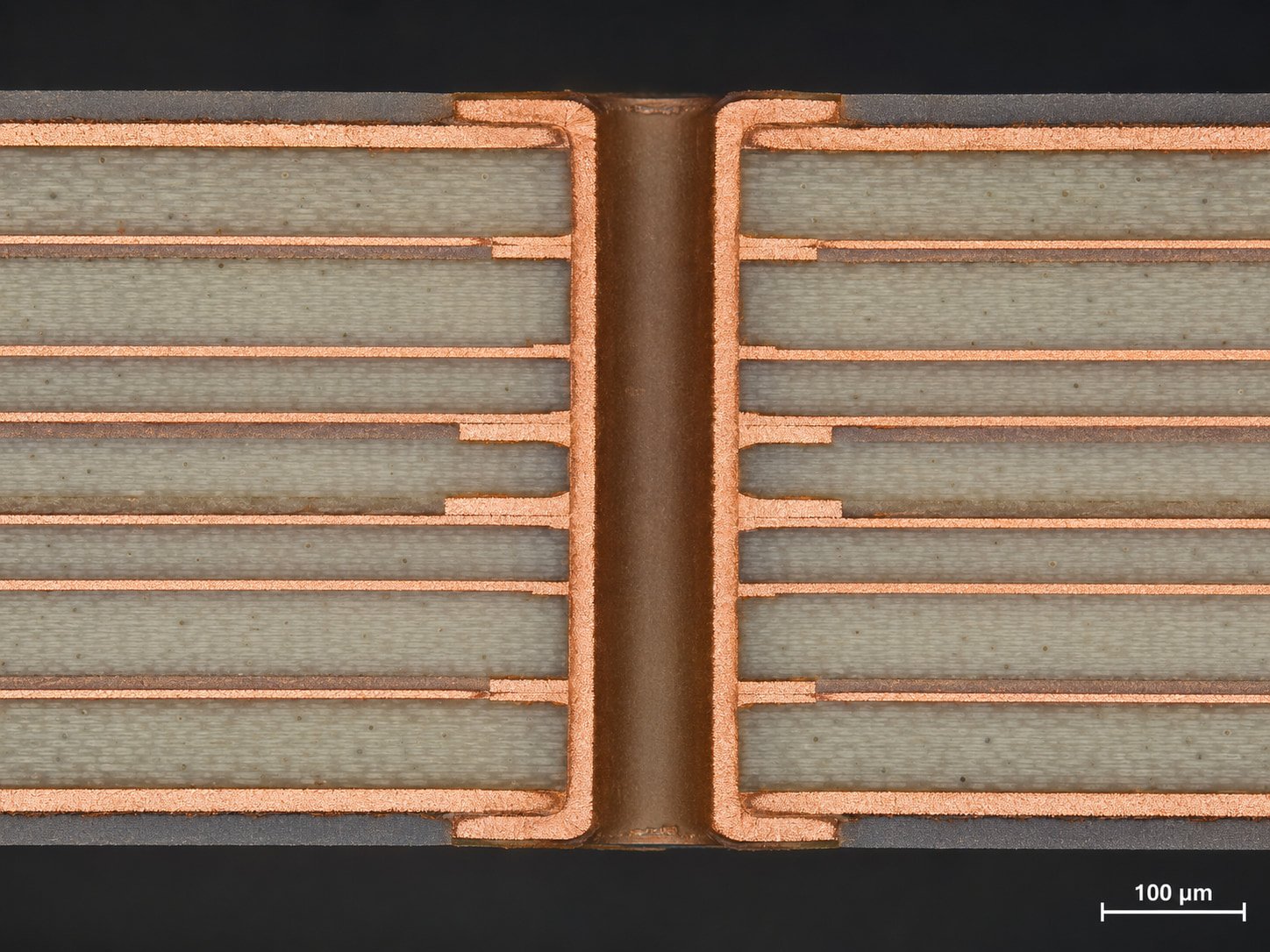
Cross-section micrograph of a multilayer RO4000 PCB showing stable plated through-holes, copper bonding, and dielectric layer structure for high-frequency circuit applications.

Avoid the Traps! 3 Core Indicators of High-Quality High-Frequency PCBs

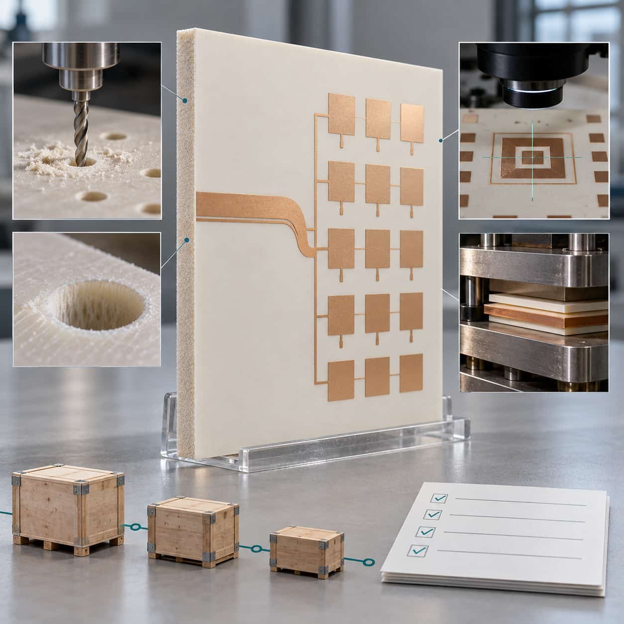
F4BM-220 PTFE laminate panel with drilling, registration and lamination challenge icons and a supply chain qualification card

F4BM-220 High-Frequency Circuit Board: Enabling Next-Generation Wireless Communication and RF Systems

Breakthrough Performance of F4BM-220 High-Frequency PCB:• Ultra-low dielectric constant Dk=2.20±0.02 • Extremely low loss factor 0.0009@10GHz • Critical applications in 5G mmWave/satellite comms/quantum tech • Precision process: LDI laser imaging with ±2% impedance control • Rigorous validation: 110GHz testing/1000 thermal cycles • Future evolution: 6G/3D integration technology

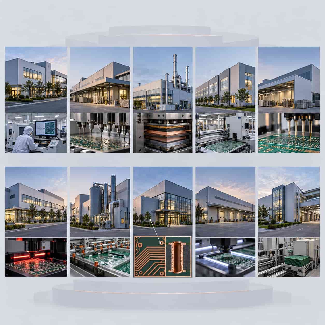
Top 10 High-Frequency & RF PCB Manufacturers in China (2025)

Three procurement phases for RF microwave PCBs each flagged with a mistake, audit magnifier and cost impact tag

Common Mistakes RF Microwave PCB Procurement Managers Make and How to Avoid Them

PCB Assembly

PCBA Services

Quality

Application

Resources

Printed Circuit Board

RF PCB

Quality

PCB Surface Finish

Printed Circuit Board

Drills & Throughplating

Profiles

PCB Stackup

Resources