A pre-order checklist for high-frequency PCB manufacturing — design files, material specs, impedance tolerances, and logistics details to prepare before you request a quote.
In wireless communication, radar, and satellite technology, the quality of your high-frequency PCB is the foundation of system performance. High-frequency boards need much tighter tolerances than standard FR-4 to maintain signal integrity and minimize dielectric loss — which is why the design intent and the specs you provide matter from day one.
At Shenzhen Xincheng’er Circuit Technology Co., Ltd., we specialize in rapid prototyping and small-to-medium batch production of microwave, RF, and inductive PCBs. Whether you are designing for 5G base stations or power amplifiers, precise specifications are the first step toward a successful build.
Below is the essential checklist of information required to start a high-frequency PCB manufacturing project.
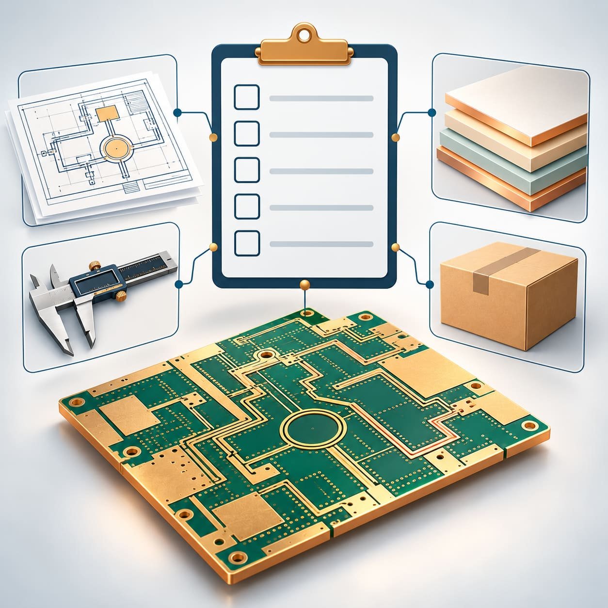
To process your order, we need complete design files. Our engineering team uses industry-standard software to review HF layouts and confirm manufacturability. Compatible formats:
High-frequency boards are defined by their materials — the dielectric constant (Dk) and dissipation factor (Df) are critical, unlike standard digital boards.
We work with specialized substrates covering dielectric constants from 2.2 to 10.6:
Surface finish affects skin-effect losses on RF boards. We offer:
For microwave and RF circuits, impedance mismatch causes signal reflection, so critical traces need precision control. Our standard tolerances:
Please specify which traces require impedance control and the target impedance in your fabrication notes — our stack-up design guide shows how layer choice shapes the result.
We aim for a seamless transition from prototyping to delivery:
We have deep manufacturing expertise in high-frequency boards for power dividers, couplers, combiners, RF antennas, and 4G/5G base stations. Our facility is optimized for the handling requirements of PTFE and ceramic-filled materials, so your microstrip and stripline designs perform exactly as simulated.
According to IPC standards for high-speed design, material consistency is the single biggest factor in HF board reliability. By sourcing directly from authorized distributors, we guarantee the Dk stability of every batch.
Quick answers on files, materials, tolerances, and ordering
Standard FR-4 has a high dissipation factor (Df), meaning it "absorbs" signal at high frequencies. Rogers materials have much lower loss and a stable dielectric constant across a wide frequency range, which is vital for RF microwave applications.
Yes. We often produce Rogers multilayer high-frequency hybrid boards where only the top layers use Rogers for signal integrity, while the inner layers use FR-4 to reduce the total cost of the PCB.
ENIG (electroless nickel immersion gold) provides a very flat surface, which is excellent for SMT components and provides good corrosion resistance. However, for extremely high frequencies (above 10 GHz), some designers prefer immersion silver to avoid the magnetic properties of nickel.
You should provide an impedance table or a readme file indicating the layer, the trace width, and the required impedance value (e.g. "Layer 1, 10 mil trace, 50 Ohm ±10%").
Send your Gerber files and fabrication notes — we will confirm manufacturability, material availability, and quote within one working day.
Send Your Design Files Fast Reply on WhatsApp