ENIG, immersion silver and immersion tin compared on insertion loss, surface roughness and RF reliability — so you can pick the right finish for your frequency band.
High-frequency PCB performance depends on much more than substrate selection. Most designers obsess over dielectric constant (Dk), dissipation factor (Df) and stack-up design, then treat the surface finish as a detail to settle at the last minute. In practice, the final metal layer applied to a high-frequency PCB has a measurable say in signal integrity, insertion loss and overall RF performance.
For 5G radios, millimeter-wave radar, satellite payloads and RF front-end modules, the finish is the last interface a signal crosses before it leaves the board. Pick the wrong one and you add conductor loss right at the point where every extra tenth of a decibel costs you range or link margin.
This guide compares the three finishes you will most often be quoted for RF work — ENIG (Electroless Nickel Immersion Gold), immersion silver and immersion tin — on electrical performance, signal loss, surface roughness and the applications each one actually fits.
At microwave and millimeter-wave frequencies, the skin effect pushes current into the outermost skin of the conductor. Above 30 GHz the penetration depth drops below 1 µm — at that point the plating effectively is the conductor surface as far as the signal is concerned, so its electrical character directly shapes transmission performance.
An ideal high-frequency PCB surface finish should offer:
The stakes are real: published measurements show that at 60 GHz, different finishes can differ by up to 0.15 dB/cm in insertion loss — enough to meaningfully cut transmission distance and system efficiency on a long RF path.
Side by side, the resistivity and loss numbers explain most of what follows:
| Surface Finish | Typical Thickness | Resistivity (×10⁻⁸ Ω·m) | Additional Loss vs Bare Copper |
|---|---|---|---|
| Immersion Silver | 0.1–0.3 μm | 1.59 | +2.12% |
| OSP | 0.2–0.5 μm | Non-metallic | Minimal |
| Immersion Tin | ~1 μm | 11.0 | ~+10% |
| ENIG | Ni 3–5 μm + Au 0.05–0.1 μm | Ni 6.99 / Au 2.44 | +19.32% |
Among mainstream finishes, immersion silver consistently posts the best RF numbers.
Silver is the most conductive metal available, with resistivity slightly below copper’s own, and the immersion layer is extremely thin — so high-frequency current keeps flowing through a highly conductive region instead of a lossy one, and conductor losses stay minimal.
For high-frequency PCB designs running at 10 GHz, 24 GHz, 60 GHz and beyond, immersion silver is usually the best balance between electrical performance and manufacturing cost.
Immersion tin solders beautifully and keeps cost down, but its conductivity is well below both copper and silver.
That higher resistivity translates into extra conductor loss — typically around 10% versus bare copper — and the penalty grows with frequency, which is why tin shows up mostly in cost-sensitive consumer products rather than serious RF hardware.
ENIG remains one of the most popular finishes in the industry, and for good reasons:
But its high-frequency reputation is often misunderstood. The problem is not the gold — it is the nickel barrier underneath. Nickel is far more resistive than copper and adds magnetic losses at microwave frequencies.
Testing shows ENIG can add nearly 20% insertion loss at 10 GHz, and more still at millimeter-wave frequencies. For an RF engineer squeezing every fraction of a decibel, that is a real design variable — worth weighing before you commit, and worth discussing with whoever runs your high-frequency multilayer PCB manufacturing line.
As frequencies climb, conductor surface roughness matters more and more: a smoother copper surface scatters less signal energy and transmits more of it cleanly.
Typical roughness values by finish:
| Surface Finish | Surface Roughness |
|---|---|
| ENIG | Ra 0.1–0.2 μm |
| Immersion Silver | ≤0.5 μm |
| Immersion Tin | Higher than silver |
On paper ENIG is the flattest of the three, yet in RF work the nickel layer underneath often cancels that flatness advantage. Immersion silver pairs a smooth surface with top-tier conductivity, which is exactly why it keeps winning in high-frequency PCB manufacturing.
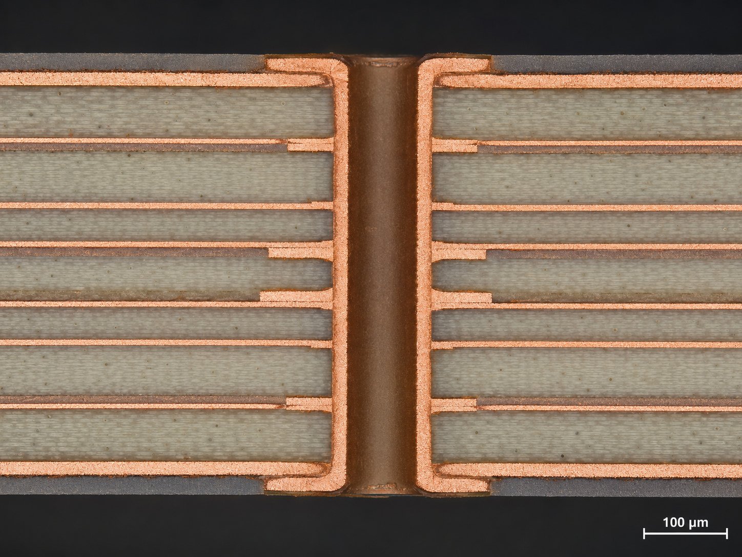
No single finish wins everywhere. The right choice depends on where the board will live and what it must survive:
Best suited for:
Many advanced RF evaluation platforms specify immersion silver for one simple reason: exceptionally low conductor loss.
Recommended for:
When shelf life and corrosion resistance outweigh a decibel of insertion loss, ENIG is still an excellent call.
Commonly used in:
For demanding microwave or millimeter-wave designs, though, it is generally not the right tool.
For designers chasing maximum RF performance, immersion silver remains the preferred surface finish for high-frequency PCB manufacturing — exceptional conductivity, minimal insertion loss and a smooth surface, all of which suit microwave and millimeter-wave systems.
ENIG keeps dominating where long shelf life and reliability rule — aerospace, medical, industrial — but go in with eyes open about the nickel-layer loss penalty.
Immersion tin brings cost and solderability advantages, and is best left to products where the signals are not pushing into the microwave range.
In the end, surface finish selection is a balance: electrical performance, reliability, manufacturing requirements and cost. Weigh them against what the board actually does, and the right choice is usually obvious.
Common questions about PCB surface finishes — for project-specific review, contact our team directly.
Immersion silver. Silver has the highest electrical conductivity of any commonly used PCB finish, and the immersion layer is thin enough that high-frequency current stays in a low-loss region — so insertion loss stays closest to bare copper.
Not because of the gold, but the nickel barrier layer beneath it. Nickel has much higher resistivity than copper and adds magnetic losses at microwave frequencies, which is why ENIG can add close to 20% insertion loss at 10 GHz.
Yes — it is widely considered one of the best choices for 5G infrastructure, RF front-end modules, microwave circuits and millimeter-wave radar, precisely because of its very low conductor loss.
It can work at lower RF frequencies, but the roughly 10% insertion-loss penalty versus bare copper makes it a poor fit for microwave and millimeter-wave systems.
Look at the whole picture: insertion loss, conductivity, surface roughness, corrosion resistance, solderability, shelf life and system reliability — then weigh them against the frequencies your board actually runs at.
Tell us your frequency band, substrate and reliability requirements. Our engineering team will compare finishes for your build, check the loss budget and quote your high-frequency PCB.
Get A Finish Review → Fast Reply on WhatsApp