High-Frequency PCB Insights & Resources

Technical guides, material comparisons and process insights on high-frequency, RF and microwave PCB manufacturing.

Rising localisation progress bar for high-frequency PCBs with an unclimbed millimetre-wave and AI computing frontier in amber

The Localization of High-Frequency PCBs: Import Dependence is Breaking, but Core Challenges in mmWave and AI Computing Persist

High-frequency PCB at the centre of low-loss, signal stability, precision trace and environmental resilience icons with satellite, base station, radar and instrument silhouettes

Unlocking the Future of Communication: Exploring the World of High-Frequency Circuit Boards

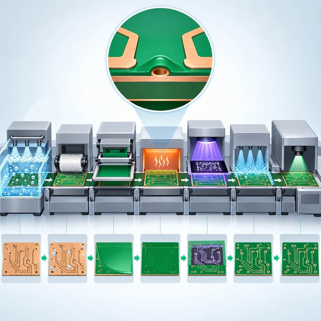
Seven-step high-frequency PCB solder mask application line from cleaning through printing, baking, exposure, development and AOI inspection

Steps and Considerations for Solder Mask Application in High-Frequency PCB Manufacturing

Rogers 4003C high-frequency board linked to MRI, CT, wearable sensor, portable monitor and microwave therapy applications

Rogers 4003 PCB Applications in Medical Devices

Rogers RO4350B laminate panel with high-reading gauges, a flat low-loss curve and radar, base station and high-speed digital applications

Rogers RO4350B High-Frequency PCB Material: A High-Performance Solution Designed for Demanding Environments

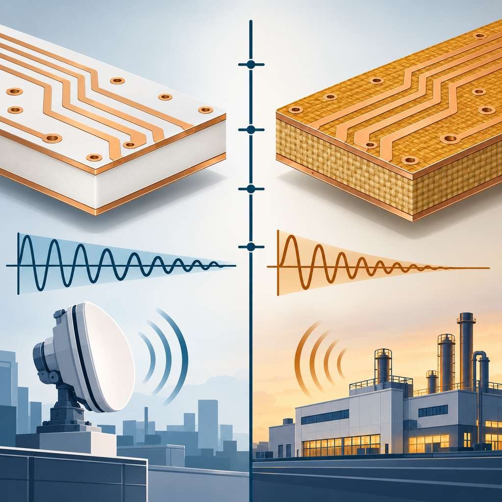
Rogers 3003 PTFE laminate and 4003C ceramic-filled laminate cross-sections compared with their loss lines and application icons

Performance and Differences Between Rogers 3003 and 4003

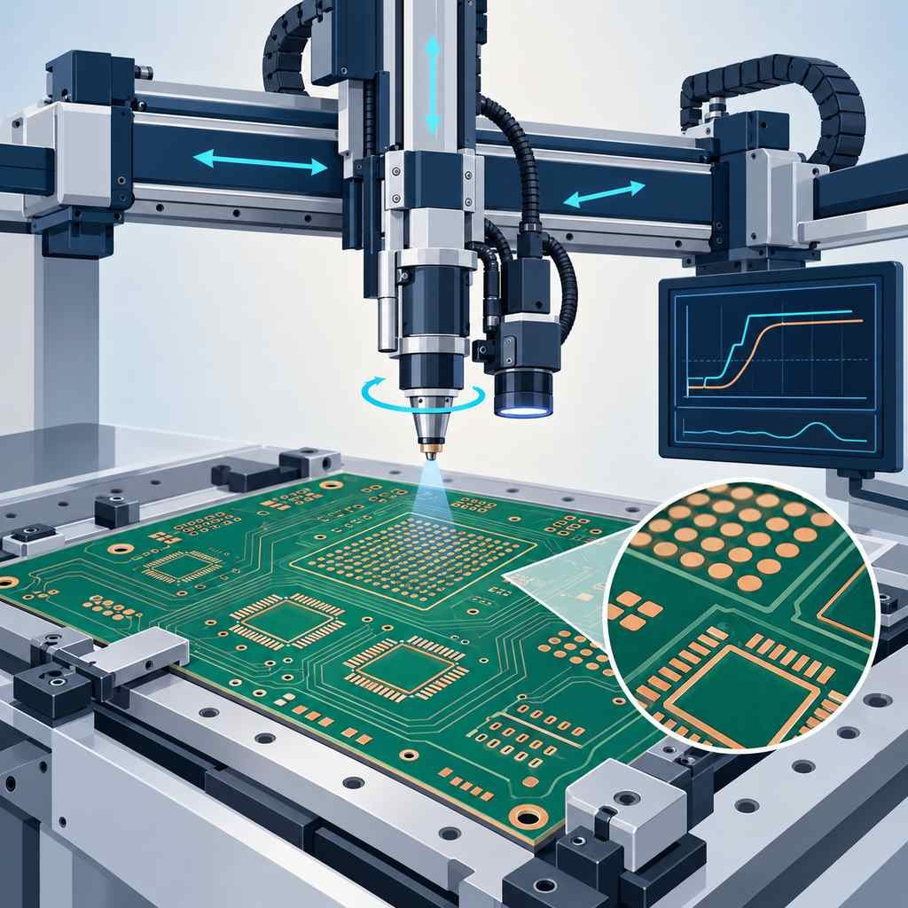
Multi-axis robotic 3D welding head with vision feedback soldering BGA and QFN joints on a high-frequency PCB

High-Frequency PCB Manufacturing: 3D Welding Process Automation Equipment

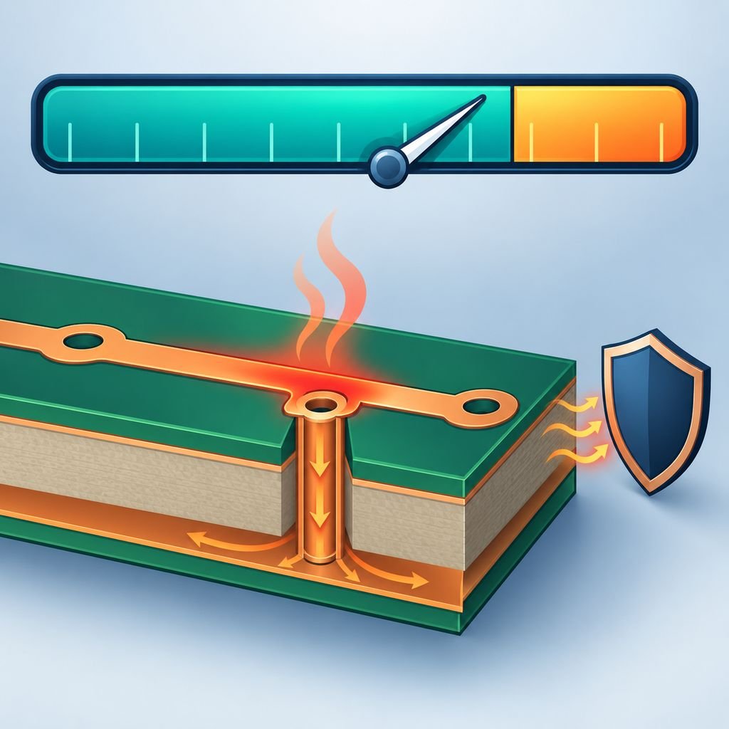
PCB current capacity bar with a needle in the safe zone and a board cross-section showing trace heating, thermal vias and a protection device

What does overload refer to in PCB manufacturing, its properties and effects?

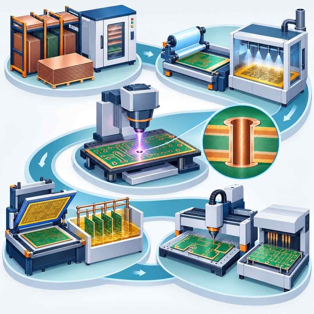
Five production phases of an RO5880 high-frequency PCB from material preparation through patterning, drilling, outer layers and final testing

Production Process of High-Frequency Circuit Board 5880

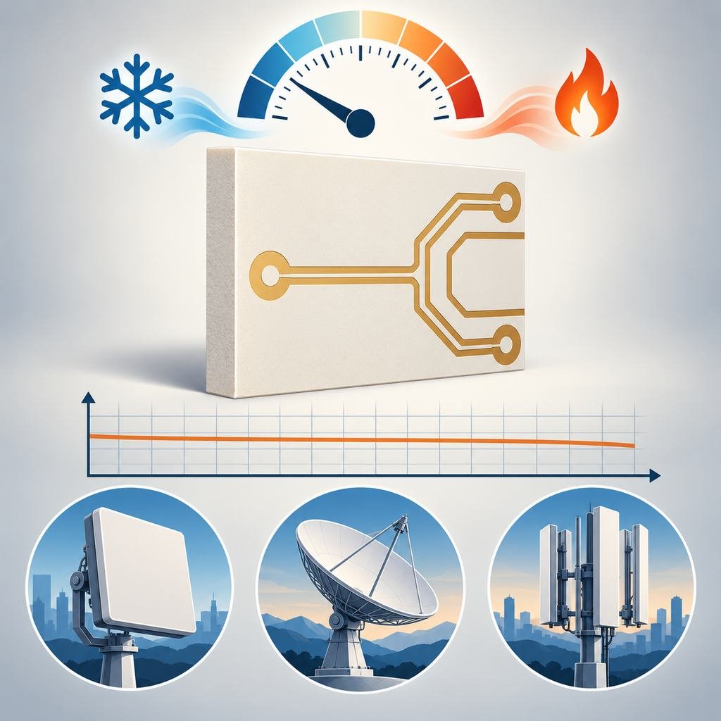
RT/duroid 3003 PTFE laminate panel with a low-reading dial, thermal range icons, a flat low-loss curve and antenna, satellite and base station silhouettes

Unique Advantages of Rogers RT/duroid® 3003

Eight process control nodes around an RO5880 high-frequency board covering storage, drilling, imaging, lamination, finish, verification, faults and environment

Key Process Considerations for Rogers RT5880 High-Frequency Circuit Boards

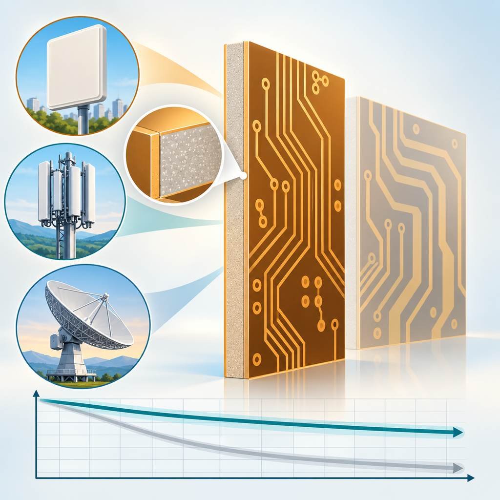
RT/duroid 4003C filled PTFE laminate panel with a narrower trace pattern than its comparison board, a magnified filler inset and a flat loss curve

Unique Advantages of Rogers RT/duroid® 4003C

PCB Assembly

PCBA Services

Quality

Application

Resources

Printed Circuit Board

RF PCB

Quality

PCB Surface Finish

Printed Circuit Board

Drills & Throughplating

Profiles

PCB Stackup

Resources