The five process steps from cleaning to testing, key control points, and an honest comparison of HASL, ENIG, tin, silver and coating treatments — plus fixes for the four most common plating defects.
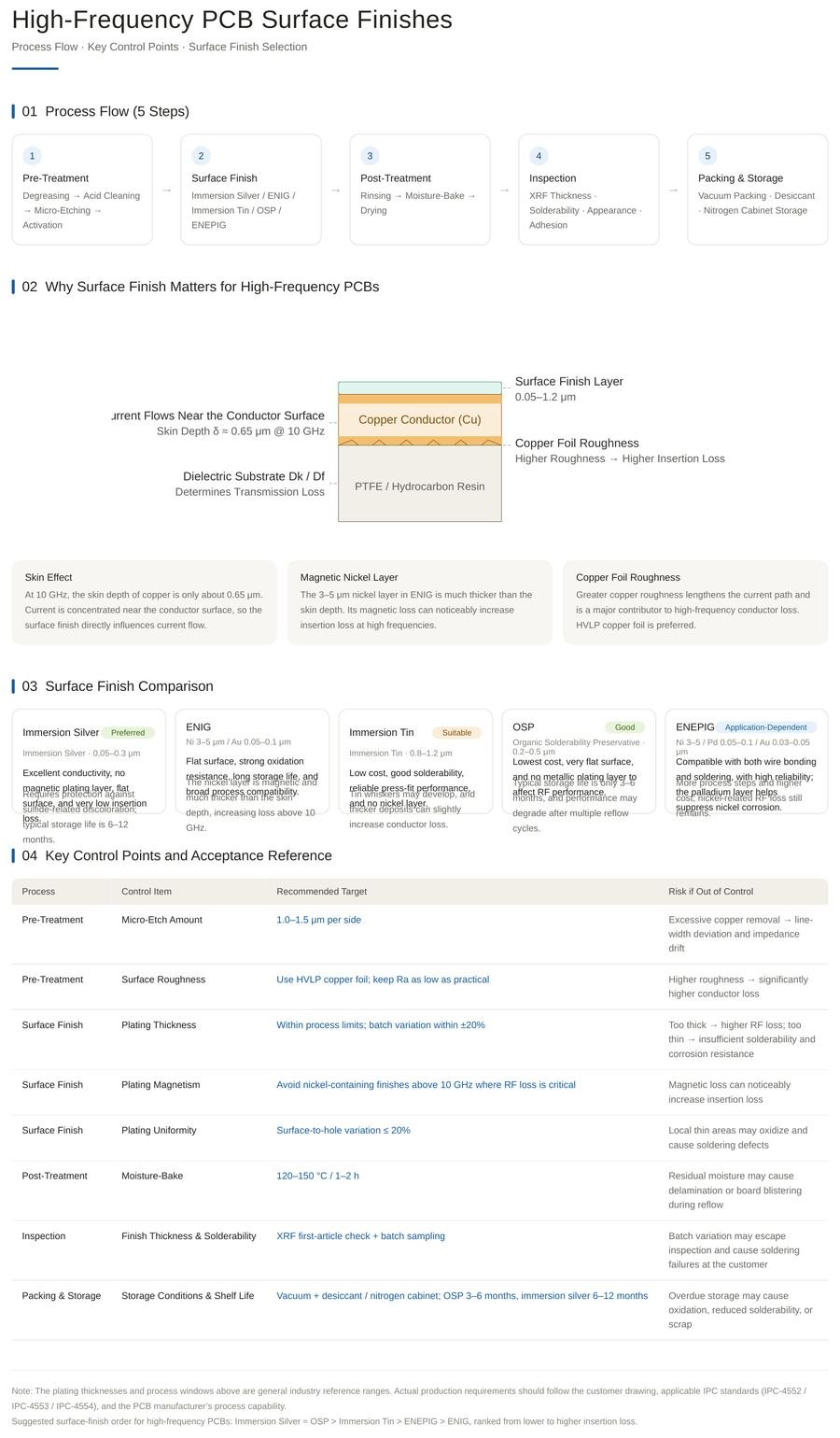
Surface treatment directly affects a board’s solderability, corrosion resistance, and electrical performance. The main steps are:
1. Cleaning. The PCB surface must be thoroughly cleaned to remove oil, dust, and impurities — using ultrasonic, solvent, or chemical cleaning.
2. Surface activation. Acid etching or plasma treatment raises surface energy and promotes metal deposition, ensuring good adhesion of subsequent layers.
3. Electroplating or chemical plating. Electroplating (current-driven) is usually used for tin and gold plating; chemical plating (currentless) is used for immersion gold and immersion tin.
4. Post-treatment. Cleaning, drying, passivation — and in some cases thermal treatment after plating — enhance the adhesion and durability of the coating.
5. Testing. Corrosion resistance, adhesion, and conductivity tests verify that the treatment quality meets design requirements.
Cleaning quality. It is the first step and must be thorough — residual impurities ruin plating quality downstream.
Activation choice. Match the activation method to the substrate to achieve sufficient surface energy for plating adhesion.
Coating thickness control. Strictly control thickness during plating; coatings that are too thick or too thin both hurt electrical performance and solderability.
Environmental control. Temperature, humidity, and bath chemistry must be held stable throughout the process.
Testing and quality control. Regular per-batch testing keeps surface treatment quality within standard and drives process-parameter optimization.
HASL (Hot Air Solder Leveling). The board is dipped in molten solder and excess is blown off with hot air. Temperature control is critical — excessive heat can damage the substrate.
Immersion gold (ENIG). A chemical plating method with excellent solderability and corrosion resistance. Deposition time and temperature must be strictly controlled for coating consistency. See our breakdown of ENIG vs plated gold vs DIG vs thick vs thin gold for layer-by-layer differences.
Tin plating. Enhances solderability and prevents substrate oxidation, applied by electroplating or chemical plating. Post-plating thermal treatment improves durability and adhesion.
Silver plating. Silver’s conductivity exceeds copper’s, making it valuable for high-frequency signal paths. Silver tarnishes readily, so anti-oxidation treatment is required for long-term stability — a trade-off we analyze in ENIG vs silver vs tin surface finishes.
Coating treatments. Protective polymer coatings improve abrasion resistance and waterproofing; material choice must balance electrical performance, thermal stability, and environmental adaptability.
Uneven coating. Usually caused by inadequate cleaning, improper activation, or poor plating control. Solution: tighten cleaning and activation control and run regular thickness testing.
Poor adhesion. Dirty substrate surface or insufficient activation. Solution: redo cleaning and activation as needed before plating.
Coating delamination. Insufficient thickness or poor material compatibility. Solution: select appropriate coating materials at the design phase and verify thickness meets standard.
Corrosion. Inadequate protection or harsh environments. Solution: apply anti-oxidation treatments and additional protective coatings.
Surface treatment for high-frequency PCBs is crucial for performance and reliability. By precisely controlling every aspect of cleaning, activation, plating, and post-treatment, manufacturers can ensure boards exhibit excellent electrical performance and stability in high-frequency applications. A disciplined process flow — backed by per-batch testing — is what turns a good laminate into a reliable finished board.
Common questions about high-frequency PCB surface treatment.
ENIG is the most common choice for high-frequency work because it offers a flat, solderable, oxidation-resistant surface with low contact resistance. Immersion silver conducts slightly better but needs anti-tarnish handling; the full comparison is in our ENIG vs silver vs tin guide.
Too thin and the coating fails to protect or solder reliably; too thick and it increases insertion loss at high frequencies and complicates wire bonding. Consistent thickness keeps electrical performance and solderability predictable.
It can, but with caveats: the high temperatures of molten solder can stress PTFE-based laminates, and the uneven surface is less suitable for fine-pitch components. ENIG or immersion silver are usually better fits.
Delamination typically comes from insufficient coating thickness or poor material compatibility. Prevention starts at design — choosing compatible stacks — and continues with verified thickness at production.
Tell us your application, soldering process and environment. Our team will recommend the right finish for your high-frequency PCB and quote your project.
Get A Quote → Fast Reply on WhatsApp