Where FR-4 ends and RO4250B begins — lamination parameters, drilling practice, and reliability testing for hybrid high-frequency stack-ups.
FR-4 and RO4250B PCB lamination processing plays a critical role in determining the performance, reliability, and manufacturability of modern electronic products. As high-frequency communication systems, automotive radar, satellite communications, and RF devices continue to evolve, engineers increasingly combine traditional FR-4 with high-frequency laminates such as RO4250B to balance performance and cost.
Understanding the material characteristics and processing requirements of both substrates is essential for achieving stable impedance control, reliable interconnections, and long-term product reliability.
FR-4 remains the most widely used PCB substrate in the industry thanks to its balance of performance and affordability.
Key characteristics: excellent mechanical strength, good electrical insulation, reliable thermal stability, strong chemical resistance, a mature and cost-effective process, and suitability for multilayer fabrication.
The dielectric constant and loss tangent are acceptable for many digital and low-frequency applications — but as operating frequencies rise, signal loss grows, which is what pushes RF and microwave designs toward alternative materials.
Typical applications: consumer electronics, industrial control, power supplies, computer motherboards, and automotive electronics.
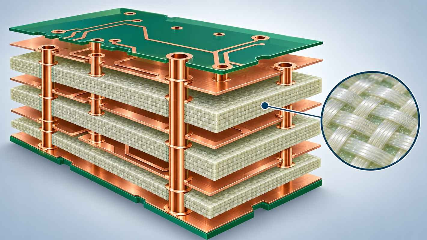
RO4250B is a high-performance laminate designed specifically for RF and microwave use, offering significantly better electrical characteristics than FR-4 at high frequencies.
Key characteristics: low dielectric constant (Dk), low dissipation factor (Df), excellent dimensional stability, high Tg, consistent impedance performance, and superior high-frequency signal transmission — exactly what GHz-range designs need for signal integrity.
Typical applications: 5G communication equipment, RF front-end modules, satellite communication systems, microwave circuits, automotive radar, and wireless infrastructure.
For detailed specifications, engineers can consult Rogers’ official documentation and IPC industry standards.
Although the two materials differ electrically, their manufacturing processes share many similarities.
Lamination process. Lamination bonds the layers under carefully controlled temperature and pressure. Critical parameters: temperature profile, pressure control, vacuum environment, resin flow management, and cure cycle duration. For hybrid stack-ups containing both FR-4 and RO4250B, pay special attention to CTE differences to prevent warpage and delamination.
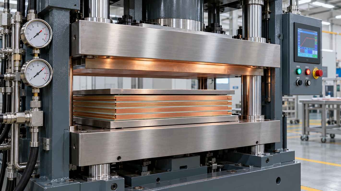
Material inspection. Check every panel before lamination for surface contamination, scratches, cracks, moisture absorption, and dimensional defects.
Layer alignment. Accurate registration is critical in multilayer work — misalignment causes impedance variation, via breakout, signal integrity issues, and assembly defects.
Prepreg selection. For FR-4 layers, prepreg quality directly affects resin flow, bonding strength, dielectric consistency, and final board thickness.
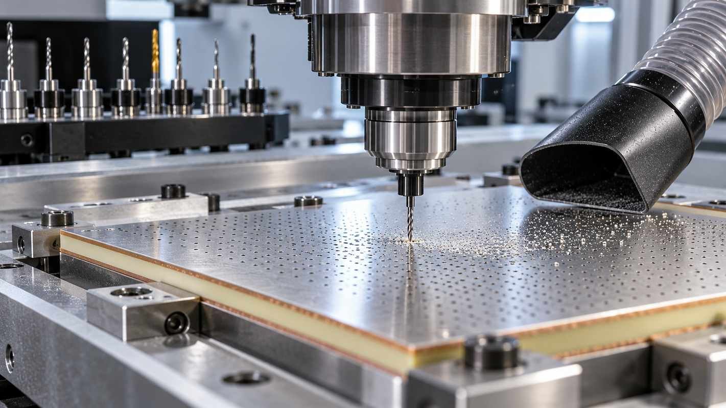
Drill bit selection. Choose bit materials and geometries that reduce burr formation, glass fiber pull-out, hole wall roughness, and thermal damage.
Process optimization. Key parameters: spindle speed, feed rate, entry material, and backup material. Optimized drilling directly improves plated-through-hole reliability.
Electrolytic copper plating. A quality plated layer shows uniform thickness, strong adhesion, low electrical resistance, and excellent thermal cycling performance. Poor plating leads to barrel cracking and intermittent failures in the field.
The stack-up directly affects impedance control and signal performance. Engineers should optimize core thickness, dielectric spacing, copper weight, reference plane placement, and controlled impedance structures.
When combining FR-4 with RO4250B, use simulation to verify impedance consistency across material interfaces — our stack-up design guide covers the method.
Thermal cycling evaluates via reliability, layer adhesion, and material stability. Damp heat testing evaluates moisture resistance, insulation performance, and long-term durability. These tests matter most for telecommunications and aerospace applications.
Production automation improves consistency, yield, and efficiency. AOI inspection catches open circuits, short circuits, etching defects, and surface contamination. X-ray inspection verifies hidden structures — BGAs and buried vias — for solder joint and internal connection quality.
On the environmental side: implement proper ESD protection throughout production, and consider halogen-free FR-4 where regulations and sustainability goals call for it.
Successful FR-4 and RO4250B lamination processing requires a comprehensive understanding of material properties, manufacturing parameters, and quality control. FR-4 remains the choice for general electronics; RO4250B earns its place where signal integrity and low loss are critical.
Optimize lamination, drilling, copper plating, stack-up design, and reliability testing, and hybrid structures will meet the demands of modern RF, microwave, and 5G systems. For the project-level view, see our pre-order information checklist.
Common questions about FR-4 and RO4250B hybrid processing
FR-4 is a general-purpose PCB material, while RO4250B is specifically designed for high-frequency applications and offers lower dielectric loss and improved signal performance.
Yes. Hybrid stack-ups combining FR-4 and RO4250B are commonly used to balance performance and manufacturing cost.
RO4250B provides a lower dielectric constant and lower loss tangent, which helps reduce signal attenuation and maintain impedance stability at high frequencies.
The primary challenges include thermal expansion differences, resin flow control, drilling quality, and maintaining dimensional stability during manufacturing.
Thermal cycling tests, damp heat testing, AOI inspection, X-ray inspection, and electrical performance verification are recommended to ensure long-term PCB reliability.
Send us your stack-up — our engineering team will review lamination parameters and quote within one working day.
Request a Hybrid Quote Fast Reply on WhatsApp