High-Frequency PCB Insights & Resources

Technical guides, material comparisons and process insights on high-frequency, RF and microwave PCB manufacturing.

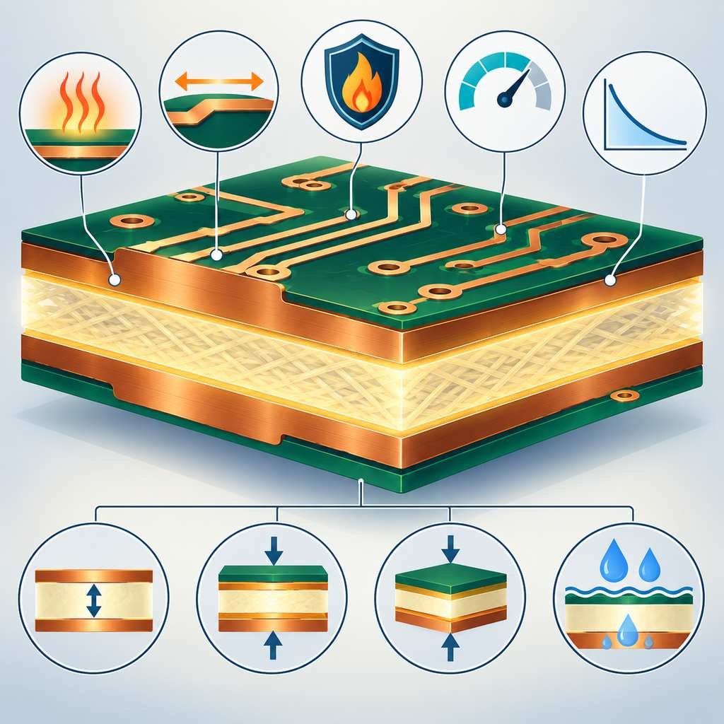
PCB cross-section highlighting the insulation layer between copper planes with callouts for heat, CTE, flame resistance and dielectric properties

Insulation layer in PCB manufacturing: It isolates conductive layers, ensuring electrical insulation and signal integrity.

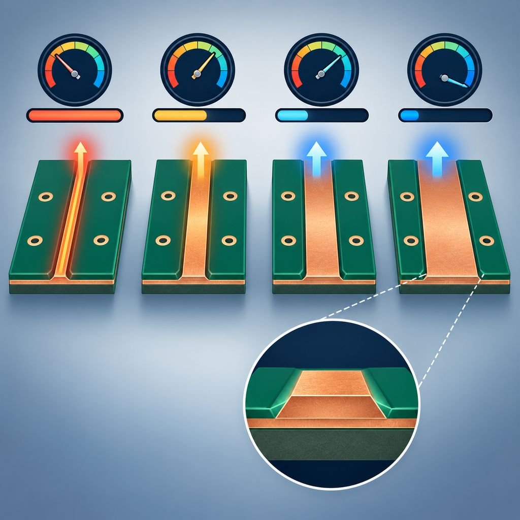
Four copper traces of increasing width carrying growing current, with an impedance dial, voltage bar and a magnified etched trace profile

PCB manufacturing, route width refers to what, performance and role?

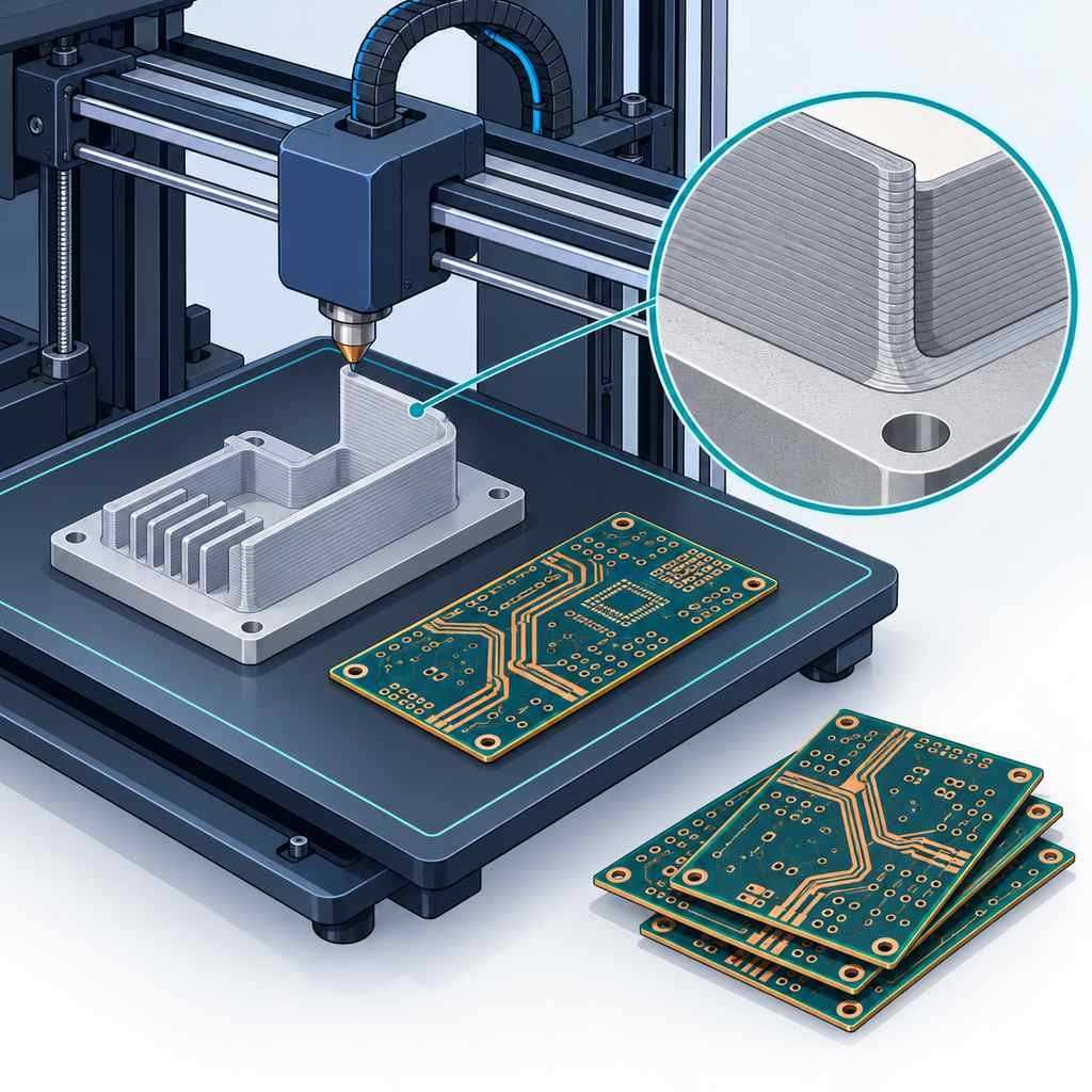
3D printer depositing a printed shielding wall and thermal structure onto a high-frequency board for rapid prototyping

3D Printing Equipment in High-Frequency PCB Manufacturing (For Rapid Prototyping)

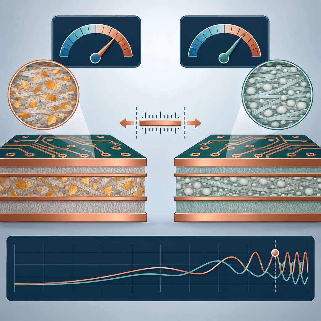
RO4350B and RO4003C laminate cross-sections under dial panels with filler textures, thermal expansion symbol and a high-frequency axis

 Rogers RO4350B/RO4003C Material Dielectric Constant Parameters

Five process standard badges for low-loss microwave PCB manufacturing covering material certification, imaging, etching, lamination and traceability

5 Key Process Standards for Low-Loss Microwave PCB Manufacturing

Five high-frequency PCB process focus areas in a ring: substrate selection, impedance control, dielectric uniformity, drilling and plating, and surface cleanliness

Key Focus Areas and Precautions in the High-Frequency PCB Manufacturing Process

RT/Duroid 5870 and 5880 PTFE High-Frequency Circuit Boards
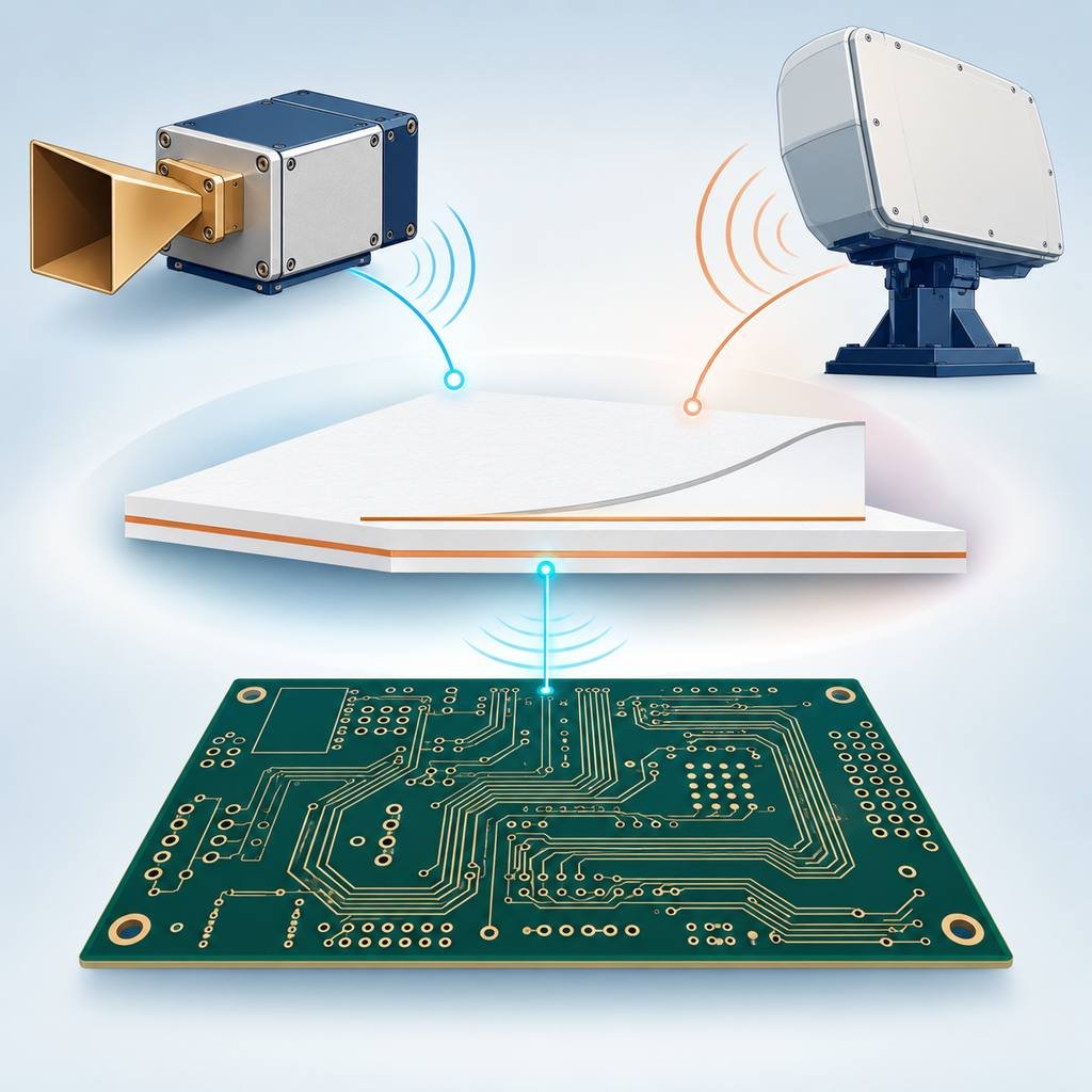
RT/duroid 5880 laminate connecting a millimetre-wave front-end, radar unit and high-speed digital board with a flat low-loss line

 Rogers 5880 Empowers Millimeter-Wave and High-Speed Designs with Ultra-Low Loss

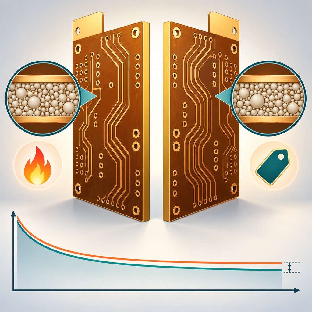
Two high-dielectric RT/duroid laminates compared back to back with heat and cost markers over their loss curves

Differences Between Rogers RT/duroid® 3210 and RT/duroid® 3010

A decision fork between process-friendly RO3010 and PTFE-based RO6010 laminates, with cost and laboratory icons over a shared low-loss line

Rogers RO3010 vs. RO6010 – How to Choose the Best Foundation for Your RF Circuit

RT6010LM high-dielectric laminate panel with a high-reading dial, a flat low-loss curve and phased array, automotive radar and instrument applications

Unique Advantages of Rogers RT6010LM

RO3210 hydrocarbon laminate panel with four gauges, a compact folded antenna and a flat low-loss curve

Unique Advantages of Rogers RO3210

PCB Assembly

PCBA Services

Quality

Application

Resources

Printed Circuit Board

RF PCB

Quality

PCB Surface Finish

Printed Circuit Board

Drills & Throughplating

Profiles

PCB Stackup

Resources