
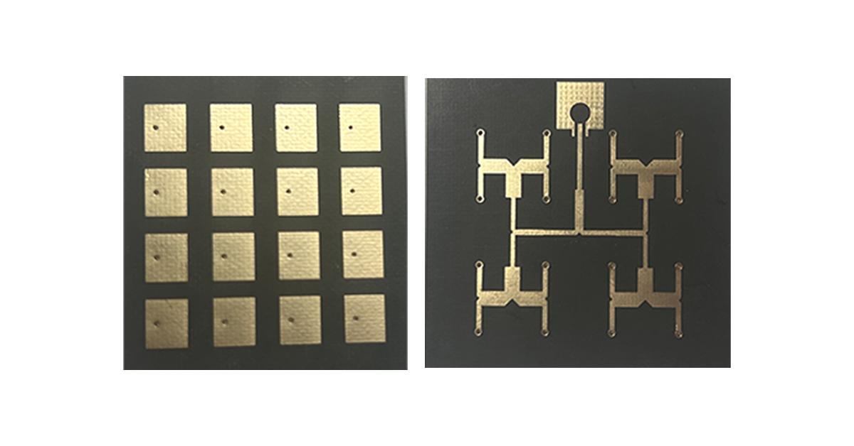
Discover the advantages of RF-35TC RF material with DK 3.50 and 0.51 mm thickness. Learn how this high-frequency PCB material supports 5G communications, radar systems, satellite navigation, automotive electronics, and IoT devices.
/rf-35tc-rf-material-dk35-high-frequency-pcb
RF-35TC RF Material: DK 3.50 High-Frequency PCB Material for Advanced RF Applications
As wireless communication systems continue to evolve toward higher frequencies, greater integration, and improved reliability, selecting the right RF material has become increasingly important. Modern applications such as 5G infrastructure, satellite communication, radar systems, automotive electronics, and IoT devices require PCB materials capable of maintaining stable electrical performance while supporting compact and lightweight designs.
Among the many high-frequency PCB materials available today, RF-35TC stands out due to its stable dielectric constant (DK = 3.50) and precisely controlled thickness (0.51 mm / 0.020 inch). These characteristics make it an excellent choice for RF and microwave circuit designs where signal integrity, impedance control, and long-term reliability are critical.
This article explores the key properties of RF-35TC, its technical advantages, and its real-world applications across multiple industries.
Understanding the Importance of RF Material Parameters
The electrical performance of any RF system begins with the substrate material.
Two of the most important material characteristics are:
Dielectric Constant (DK)
Material Thickness
Together, these parameters determine signal propagation speed, impedance stability, insertion loss, and overall RF system performance.
Image 1: RF-35TC high-frequency PCB laminate used for RF and microwave circuit fabrication.
RF-35TC Dielectric Constant (DK = 3.50)
The dielectric constant directly influences how RF signals propagate through a PCB substrate.
A material with an excessively high dielectric constant may cause:
Increased signal loss
Reduced signal propagation speed
Greater phase distortion
Conversely, materials with very low dielectric constants may require larger circuit dimensions, limiting integration density.
The DK value of 3.50 represents a well-balanced solution.
Benefits of DK 3.50
Stable impedance control
Reduced signal distortion
Predictable signal propagation
Improved phase consistency
Enhanced RF circuit design flexibility
More importantly, RF-35TC maintains excellent dielectric stability across a wide range of frequencies and environmental conditions, helping engineers achieve reliable performance in demanding RF applications.
Thickness Control: 0.51 mm (0.020 Inch)
As electronic devices continue to become smaller and lighter, PCB thickness plays an increasingly important role.
RF-35TC utilizes a standard thickness of 0.51 mm, providing an ideal balance between mechanical strength and miniaturization.
Advantages of 0.51 mm Thickness
Supports compact product designs
Reduces overall device weight
Maintains structural integrity
Improves impedance consistency
Simplifies multilayer RF PCB stackup design
This thickness works particularly well in antenna structures, RF modules, and microwave circuits where dimensional accuracy directly affects electrical performance.
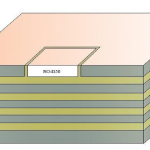
Image 2: Cross-sectional structure of RF-35TC laminate showing dielectric thickness and copper layers.
Why RF-35TC Is Ideal for High-Frequency PCB Applications
High-frequency PCB materials must provide more than just favorable electrical characteristics.
They must also deliver:
Long-term reliability
Thermal stability
Moisture resistance
Mechanical durability
Manufacturing consistency
RF-35TC is engineered to address all of these requirements simultaneously.
The combination of DK 3.50 and precise thickness control allows engineers to achieve predictable impedance values while minimizing insertion loss and signal reflections.
This makes RF-35TC particularly suitable for microwave and RF circuit designs operating in challenging environments.
5G Communication Applications
The rollout of 5G networks has created unprecedented demand for advanced RF materials.
Both Sub-6 GHz and millimeter-wave systems require substrates capable of maintaining stable electrical performance under varying environmental conditions.
Benefits for 5G Infrastructure
RF-35TC helps support:
High-frequency antenna arrays
Massive MIMO systems
RF front-end modules
Small-cell base stations
Beamforming networks
Its stable dielectric constant minimizes phase variations across antenna elements, improving signal synchronization and network efficiency.
The thin 0.51 mm construction also enables more compact antenna designs for both infrastructure and user devices.
Image 3: RF-35TC material used in 5G antenna and RF module applications.
Satellite Navigation and Radar Systems
Satellite communication and radar systems demand exceptional signal stability and environmental reliability.
These applications often operate in:
Extreme temperatures
High humidity conditions
Strong electromagnetic environments
RF-35TC provides the electrical consistency needed to maintain signal accuracy under these conditions.
Typical Applications
GPS antennas
GNSS receivers
Weather radar systems
Air traffic control equipment
Aerospace communication modules
Defense radar platforms
The stable DK value helps maintain accurate signal timing and phase control, which are essential for navigation and radar performance.
Automotive Electronics and IoT Devices
The rapid growth of connected vehicles and smart devices is driving demand for compact RF modules.
RF-35TC is increasingly used in:
Automotive Applications
Vehicle radar sensors
V2X communication systems
ADAS modules
Telematics systems
IoT Applications
Smart sensors
Industrial wireless devices
Smart home products
Asset tracking systems
Its reliable performance supports both miniaturization and long-term operational stability.
Advanced Manufacturing and Quality Control
The performance consistency of RF-35TC is achieved through advanced material engineering and strict manufacturing controls.
Material Development
The substrate utilizes carefully optimized composite formulations designed to balance:
Electrical properties
Mechanical strength
Thermal resistance
Moisture resistance
Precision Manufacturing
Advanced processing techniques ensure:
Tight dielectric constant tolerance
Accurate thickness control
Excellent dimensional stability
Consistent batch-to-batch performance
Comprehensive Testing
Each production batch undergoes rigorous testing including:
Dielectric constant measurement
Thickness verification
Mechanical strength testing
Environmental reliability testing
Thermal stability evaluation
These quality control procedures ensure reliable performance in critical RF applications.
Comparing RF-35TC with Traditional PCB Materials
| Property | RF-35TC | Standard FR-4 |
|---|---|---|
| Dielectric Constant Stability | Excellent | Moderate |
| High-Frequency Loss | Low | Higher |
| Impedance Control | Superior | Limited |
| RF Performance | Excellent | Moderate |
| Signal Integrity | Excellent | Good |
| 5G/Radar Suitability | Highly Recommended | Not Recommended |
For engineers designing RF systems above several GHz, RF-35TC offers significant performance advantages over conventional FR-4 materials.
Conclusion
RF-35TC has established itself as a highly capable high-frequency PCB material by combining a stable dielectric constant of DK 3.50 with a precisely controlled thickness of 0.51 mm. These characteristics provide a reliable foundation for RF system designers seeking optimal signal integrity, impedance stability, and long-term reliability.
Whether deployed in 5G communication infrastructure, satellite navigation equipment, radar systems, automotive electronics, or IoT devices, RF-35TC delivers the performance consistency required by modern RF applications.
As wireless technologies continue to evolve toward higher frequencies and greater integration, materials such as RF-35TC will remain essential enablers of next-generation electronic systems.